Monday, January 25, 2010

The Single-Phase Transformer


Objective:

  • To study the voltage and current ratios of a transformer.
  • To learn about transformer-exciting currents, volt-ampere capacity and short-circuit currents.
Discussion:

Transformers are probably the most universally-used pieces of equipment in the electrical industry. They range in size from miniature units in transistor radios to huge units, weighing tons, used in central power distributing stations. However, all transformers have the same basic properties which you are about to examine.

When mutual induction exists between two coils or windings, a change in current through one induces a voltage in the other. Every transformer has a primary winding and one or more secondary windings. The primary winding receives electrical energy from a power source and couples this energy to the secondary winding by means of a changing magnetic field. The energy appears as an electromotive force across the secondary winding, and if a load is connected to the secondary, the energy is transferred to the load. Thus, electrical energy can be transferred from one circuit to another, with no physical connection between the two. Transformers are indispensable in AC power distribution, since they can convert electrical power at a given current and voltage into an equivalent power at some other current and voltage.

When a transformer is in operation, AC currents flow in its windings and an alternating magnetic field is set-up in the iron core. As a result, copper and iron losses are produced which represents active power (watts) and causes the transformer to heat up. Establishing a magnetic field requires reactive power (var) which is drawn from the power line. For these reasons the total power delivered to the primary winding is always slightly larger than the total power delivered by the secondary winding. However, we can say, to a good approximation, that in most transformers:

a) Primary Power (watts) = Secondary Power (watts)
b) Primary Volt-amperes (VA) = Secondary Volt-amperes (VA)
c) Primary vars = Secondary vars.

When the primary voltage is raised beyond its rated value, the iron core (laminations) begins to saturate, and the magnetizing (exciting) current increases rapidly.

Transformers are subject to accidental short-circuits caused by natural and man-made disasters. The short-circuit currents can be very large and, unless interrupted, will quickly burn out a transformer. It is the purpose of this Experiment to show these major points.

Equipment Required:
  • A Single Phase Transformer
  • Power Supply
  • AC Ammeter
  • AC Voltmeter
  • Wires
Procedure:
CAUTION!!!
High voltages are Present In the Experiment! Do not make any connections with the power on! The power should be turned off after completing each individual measurement!!!

o 1. Examine the construction of the Single-Phase Transformer paying particular attention to the transformer, connection terminals and the wiring.

  1. The transformer core is made up of thin sheets (lamentations) of steel. Identify it.

  2. Note that the transformer windings are brought out to terminals mounted on the transformer coil.
  3. Note that these windings are then wired to the connection terminals mounted on the module face.
o 2. Identify the three separate transformer windings maked on the module face:
  1. List the rated voltage for each of the three windings:
Terminals 1 to 2 = 220 V ac
Terminals 3 to 4 = 380 V ac
Terminals 5 to 6 = 220 V ac

  1. List the rated voltage between the following connection terminals:
     Terminals 3 to 7 = 190 V ac
     Terminals 7 to 8 = 139 V ac
     Terminals 8 to 4 = 51 V ac
     Terminals 3 to 8 = 329 V ac
     Terminals 7 to 4 = 190 V ac
     Terminals 5 to 9 = 110 V ac
     Terminals 9 to 6 = 110 V ac

  1. List the rated current for each of the following connections:
Terminals 1 to 2 = 0.25 A ac
Terminals 3 to 4 = 0.15 A ac
Terminals 5 to 6 = 0.25 A ac
Terminals 3 to 7 = 0.15 A ac
Terminals 8 to 4 = 0.15 A ac

o 3. Using the lowest range of our ohmmeter, measure and record the DC resistance of each winding:
Terminals 1 to 2 = 880 Ω
Terminals 3 to 4 = 2533.333 Ω
Terminals 3 to 7 = 1266.667 Ω
Terminals 7 to 8 = 926.667 Ω
Terminals 8 to 4 = 340 Ω
Terminals 5 to 6 = 880 Ω
Terminals 5 to 9 = 440 Ω
Terminals 9 to 6 = 440 Ω

o 4. Now we measure the unloaded secondary voltages with 220 V ac applied to the primary winding.


a. Connect the circuit shown in Figure-1.
b. Turn on the power supply and adjust for 220 V ac as indicated by the voltmeter across the power supply terminals 4 to N.
c. Measure and record the output voltage E2.
d. Return the voltage to zero and turn off the power supply.
e. Repeat ( b, c and d) measuring the output voltage E2 for each of the listed windings.
f. Winding 1 to 2 = 220 V ac
Winding 3 to 4 = 380 V ac
Winding 5 to 6 = 220 V ac
Winding 3 to 7 = 185 V ac
Winding 7 to 8 = 138 V ac
Winding 8 to 4 = 50 V ac
Winding 5 to 9 = 108 V ac
Winding 9 to 6 = 106 V ac

o 5. a. We measured voltage correspond well with the rated values. But we have very something difference between the rated values and the measured values due to different kind of losses which is negligible.
b. The current for which the magnetic flux produced is called magnetizing current. The current I1 is associated with the magnetic flux so here I1 is magnetizing current. We measure it.

o 6. Windings 1 to 2 and 5 to 6 each have 1100 turns of wire. Winding 3 to 4 has 1900 turns. Calculate the following turn ratios:


o 7. a. Connect the circuit shown in Figure-2. Notice that current meter I2 short-circuits winding 5 to 6.


b. Turn on the power supply and gradually increase the voltage until the short-circuit current I2 is 0.2 A ac.
c. Measure and record E1, I1, and I2.
I1 = 0.4 A ac
E1 = 30 V ac
I2 = 0.2 A ac
  1. Return the voltage to zero and turn off the power supply.
  2. Calculate the current ratio:


  1. For a transformer the turn and current ratio are inversely equal. So theoretically the voltage and current ratio is not equal. Because-


Figure - 3

o 8. a. Connect the circuit shown in Figure-3. Notice that winding 3 to 4 is short-circuited by the current meter I3.
b. Turn on the power supply and gradually increase the voltage until the current through the primary winding I1, is 0.2 A ac.
c. Measure and record I3 and E1.
I3 = 0.12 A ac
E1 = 18 V ac
d. Return the voltage to zero and turn off the power supply.
e. Calculate the current ratio:


o 9. Now we determine the effect of core saturation upon the exciting current of a transformer.

a. Connect the circuit shown in Figure-4. Notice that power supply terminals 4 and 5 are now being used. These terminals will furnish variable 0 to 380 V ac.
b. Turn on the power supply and adjust for 50 V ac as indicated by the voltmeter across power supply terminals 4 to 5.
c. Measure and record the exciting-current I1 and the output voltage E2 for each of the input voltages listed in Table-1.
d. Return the voltage to zero and turn off the power supply.

E1
V ac
I1
mA ac
E2
V ac
50
0
45
100
0
95
150
0
145
200
0
198
250
0.1
240
300
0.2
298
350
0.3
340
400
0.5
378


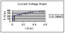
o 10. a. Plot our recorded current values on the graph of Figure-5. Draw a smooth curve through our plotted points.
b. Note that the magnetizing current increase rapidly after a certain input voltage has been reached.
c. When the voltages increase regularly; the current is increase. One time they are in saturation point.
Transformer Regulation


Objective:

  • To study the voltage regulation of the transformer with varying loads.
  • To study transformer regulation with inductive and capacitive loading.

Discussion:

The load on a large power transformer in a sub-station will vary from a very small value in the early hours of the morning to a very high value during the heavy peaks of maximum industrial and commercial activity. The transformer secondary voltage will vary somewhat with the load and, because motors and incandescent lamps and heating devices are all quite sensitive to voltage changes, transformer regulation is of considerable importance. The secondary voltage is also dependent upon whether the power factor of the load is leading, lagging or unity. Therefore, it should be known how the transformer will behave when it is loaded with a capacitive, an inductive or a resistive load.

If a transformer were perfect (ideal) its windings would have no resistance. Furthermore, it would require no reactive power (vars) to set up the magnetic field within it. Such a transformer would have perfect regulation under all load conditions and the secondary voltage would remain absolutely constant. But, practical transformers do have winding resistance and they do require reactive power to produce their magnetic fields. The primary and secondary winding possess, therefore, an overall resistance R and an overall reactance X. The equivalent circuit of a power transformer having a turn ratio of 1 to 1, can be approximated by the circuit shown in Figure-1. The actual transformer terminals are P1 P2 on the primary side and S1 S2 on the secondary.

In between these terminals we have shown the transformer as being composed of a perfect (ideal) transformer in series with impedance consisting of R and X, which represents its imperfections. It is clear that if the primary voltage is held constant, then the secondary voltage will vary with loading because of R and X.

An interesting feature arises with a capacitive load, because partial resonance is set up between the capacitance and the reactance X so that the secondary voltage E2 may actually tend to rise as the capacitive load value increases.


Equipment Required:
  • A Single Phase Transformer
  • Power Supply
  • Resistive, Capacitive and Inductive Load
  • AC Ammeter
  • AC Voltmeter
  • Wires

Procedure:
CAUTION!!!
High voltages are Present In the Experiment! Do not make any connections with the power on! The power should be turned off after completing each individual measurement!!!

1. Using Single-Phase Transformer, Power Supply, Resistive Load, AC Ammeter and AC Voltmeter, connect the circuit shown in Figure-2.

2. a. Place all of the Resistive Load switches in their open position for zero load current.

b. Turn on the power supply and adjust for exactly 220 V ac as indicated by voltmeter E1.

c. Measure and record in Table-1 the input current I1, the output current I2 and the output voltage E2.

d. Adjust the load resistance ZL to 4400 Ω. Make sure that the input voltage remains at exactly 220 V ac. Measure and record I1, I2 and E2.

e. Repeat (d) for each of the listed values in Table-1.

f. Return the voltage to zero and turn off the power supply.

ZL
(ohms)
I2
(mA ac)
E2
(V ac)
I1
(mA ac)
Infinitive
0
210
0
4400
0.05
215
0.06
2200
0.095
210
0.11
1467
0.14
200
0.15
1100
0.18
198
0.19
880
0.225
195
0.23


3. a. Calculate the transformer regulation using the no-load and full-load output voltage from Table-1.


b. For different value of load resistance, we can see the primary and secondary winding VA is not equal. For fixed value of E1 is 220 V ac and for decreasing load resistance, the primary winding current I1 increasing, the secondary winding current I2 increasing and voltage E2 decrease. For every value of load resistance, we can measure the primary winding VA always greater then the secondary winding VA.

4. a. Repeat procedure 2 using the Inductive Load in place of the Resistive Load.
    b. Record our measurements in Table-2.

ZL
(ohms)
I2
(mA ac)
E2
(V ac)
I1
(mA ac)
Infinitive
0
210
0
4400
0.05
210
0.06
2200
0.10
200
0.11
1467
0.14
198
0.15
1100
0.17
193
0.19
880
0.22
185
0.23

5. a. Repeat procedure 2 using the Capacitive Load in Place of the Resistive Load.
    b. Record our measurements in Table-3.

ZL
(ohms)
I2
(mA ac)
E2
(V ac)
I1
(mA ac)
Infinitive
0
210
0
4400
0.055
215
0.05
2200
0.11
223
0.12
1467
0.155
230
0.16
1100
0.23
235
0.21
880
0.25
240
0.25

6. Now we construct an output voltage E2 vs output current I2 regulation curve for each type of transformer load.

a. Plot recorded values of E2 (at each value of I2 listed in Table-1) on the graph of Figure-1.
b. Draw a smooth curve through plotted points. Label this curve “Resistive Load”.
c. Repeat (a) for the Inductive (Table-2) and Capacitive (Table-3) Loads. Label these curves “Inductive Load” and “Capacitive Load”.


The AutoTransformer


Objective:

  • To study the voltage and current relationship of an autotransformer.
  • To learn how to connect a standard transformer as an autotransformer.
Discussion:

There is a special type of transformer which physically has only one winding. Functionally, though, the one winding serves as both the primary and secondary. This type of transformer is called an autotransformer. When an autotransformer is used to step up the voltage, part of the single winding acts as the primary, and the entire winding acts as the secondary. When an autotransformer is used to step down the voltage, the entire winding acts as the primary, and part of the winding acts as the secondary.

Figure-1 and Figure-2 show autotransformers connected for both step-up and step-down operation.

The action of the autotransformer is basically the same as the standard two-winding transformer. Power is transferred from the primary to the secondary by the changing magnetic field, and the secondary in turn, regulates the current in the primary to set up the required condition of equal primary and secondary power. The amount of step-up or step-down in voltage depends on the turn’s ratio between the primary and secondary, with each winding considered as separate, even though some turns are common to both the primary and secondary.

Voltages and currents in the various windings can be found by two simple rules:

a) Primary apparent power (VA) equals Secondary apparent power (VA).
(VA)P = (VA) S---------------- (1)
EPIP = ESIS------------------ (2)
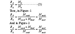
b) The primary (source) voltage and the secondary (load) voltage are directly proportional to the number of turns N.


These equations depend upon one important fact, that voltage EA to B and EB to C add in the same direction and do not oppose each other. We have assumed that the voltages are in phase.

The load current, of course, cannot exceed the current carrying capacity of the winding. Once this is known it is relatively easy to calculate the VA load which a particular autotransformer can supply.

A disadvantage of the autotransformer is the lack of isolation between the primary and secondary circuits, because the primary and secondary both use some of the same turns.
Equipment Required:
  • A Single Phase Transformer
  • Power Supply
  • Resistive Load
  • AC Ammeter
  • AC Voltmeter
  • Wires
Procedure:
CAUTION!!!
High voltages are Present In the Experiment! Do not make any connections with the power on! The power should be turned off after completing each individual measurement!!!

1. Using a Single-Phase Transformer, Power Supply, Resistive Load, AC Ammeter and AC Voltmeter, connect the circuit shown in Figure-3. Note that winding 5 to 6 is connected as the primary winding across the 220 V ac source. The centre tap of the winding, terminal-9 is connected to one side of the load and the 6 to 9 portion of the primary winding is connected as the secondary winding.

2. a. Place all of the Resistive Load switches in their open positions for zero loads current.

b. Turn on the power supply and adjust for exactly 220 V ac as indicated
by voltmeter E1. (This is the rated voltage for winding 5 to 6).

c. Adjust the load resistance RL to 4400 Ω.

d. Measure and record currents I1, I2 and the output voltage E2.
I1 = 0.01 A ac
I2 = 0.02 A ac
E2 = 105 V ac
      e. Return the voltage to zero and turn off the power supply.


3. a. Calculate the apparent power in the primary and secondary circuits.
        E1 (220) × I1 (0.01) = 2.2 (VA) P
        E2 (105) × I2 (0.02) = 2.1(VA) S
    b. The primary and secondary apparent powers are not equal. Because we can see from Figur-1; the primary winding turns is greater than the secondary winding turns. So the secondary winding apparent power is less than the primary winding apparent power. This is a step-down Autotransformer.

4. Connect the circuit shown in Figure-3. Notice that winding 6 to 9 is now connected as the primary winding across the 110 V ac source. The 5 and 6 winding is now connected as the secondary winding.


5. a. Place all of the Resistive Load switches in their open positions for zero load current.
   b. Turn on the power supply and adjust for exactly 110 V ac as indicated by voltmeter E1.(This is the rated voltage for winding 6 to 9.
   c. Adjust the load resistance RL to 2200 Ω.
   d. Measure and record currents I1, I2 and the output voltage E2.
I1 = 0.01 A ac
I2 = 0.10 A ac
E2 = 210 V ac
   e. Return the voltage to zero and turn off the power supply.

6. a. Calculate the apparent power in the primary and secondary circuits.
        E1 (110) × I1 (0.01) = 1.1 (VA) P
        E2 (210) × I2 (0.10) = 21(VA) S
    b. The primary and secondary apparent powers are not equal. Because we can see from Figur-2; the primary winding turns is less than the secondary winding turns. So the secondary winding apparent power is greater than the primary winding apparent power. This is a step-up Autotransformer.